From Insight to Reality.
The device is a physical, tested compnonet ready for controlled real-world pilot deployment.
University-Backed
Supported by physical testing and ongoing collaboration with engineering experts at Ulster University and the University of Nottingham.
Underpinned by Science
Validated by an independent physics paper exploring subsurface hydraulic dynamics and the venting mechanism.
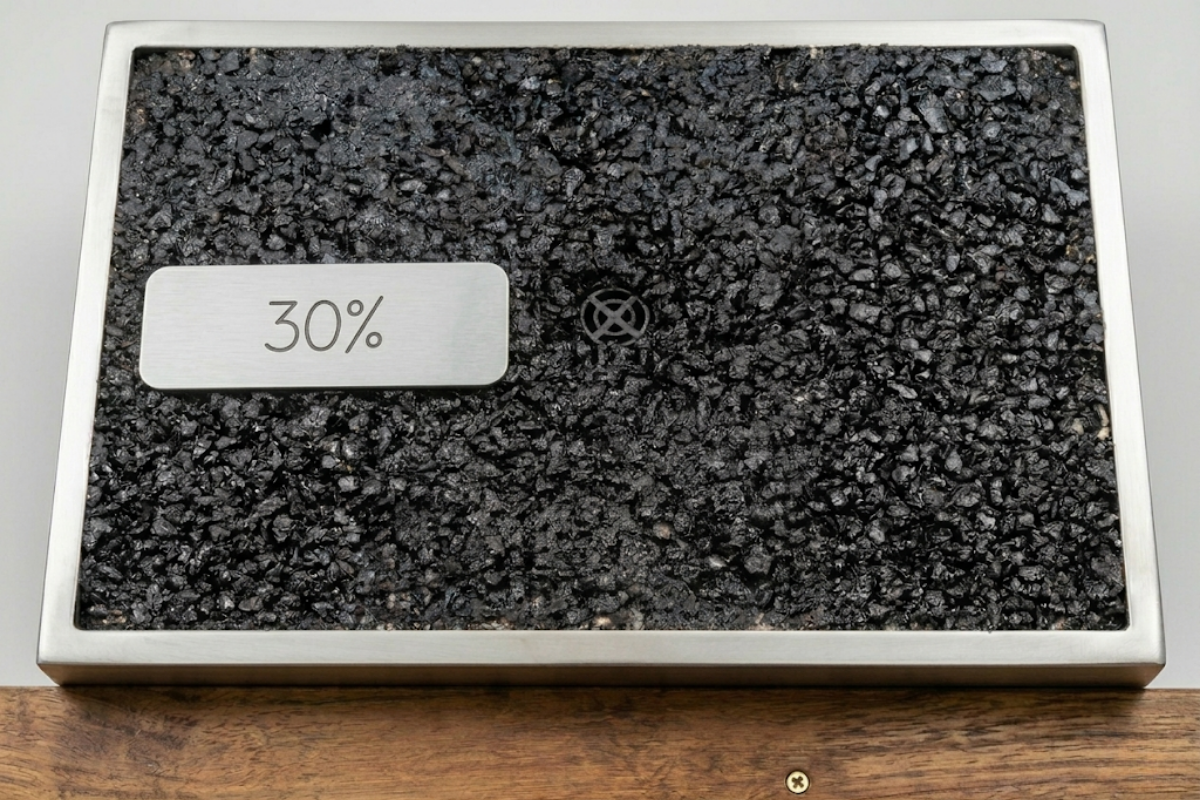
Nylon/Glass 70/30
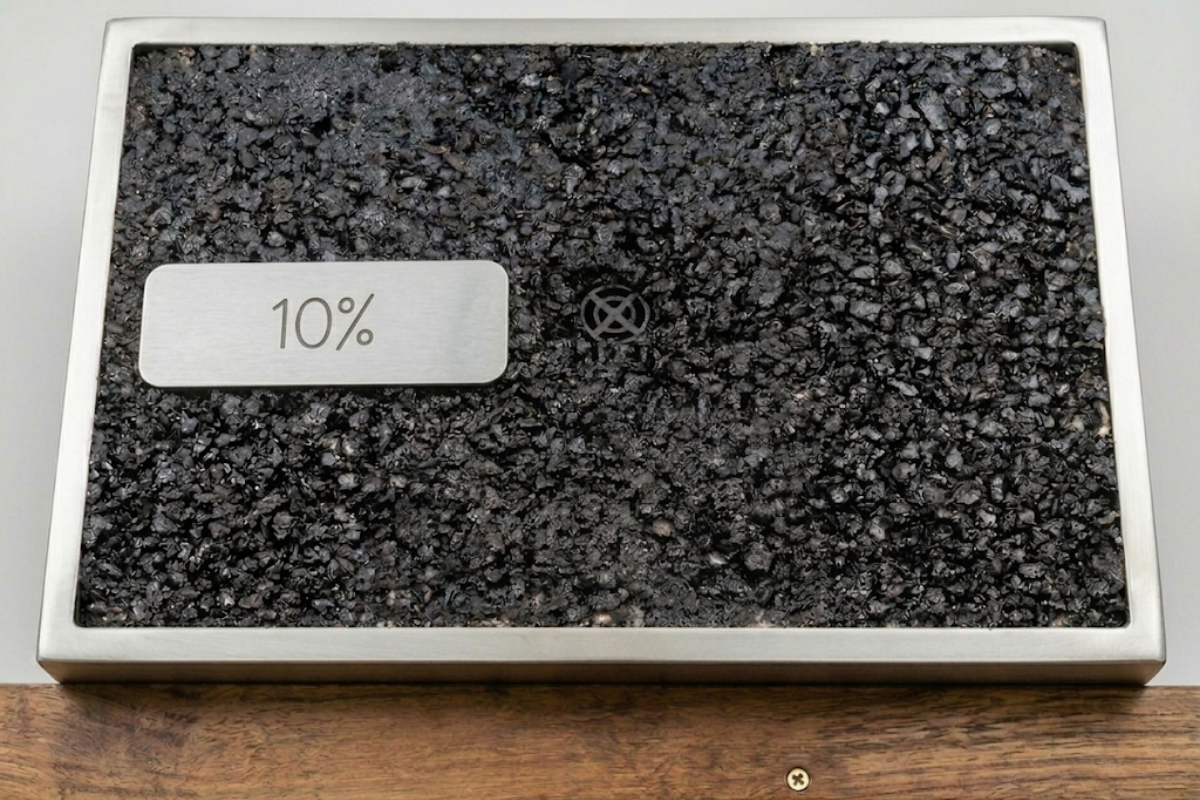
Nylon/Glass 90/10
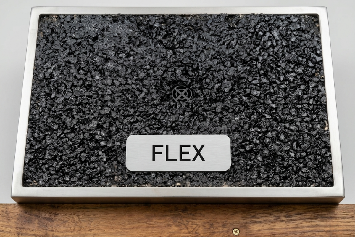
TPE 80A (Flex)
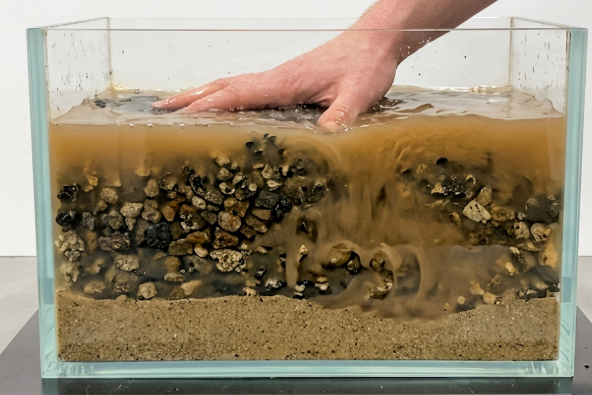
Subsurface Mobilisation (Hydraulic Pumping Test)
Under saturated conditions, applied pressure mobilises water and disperses fines. Water visibly migrates away from the central area, demonstrating active subsurface drainage.
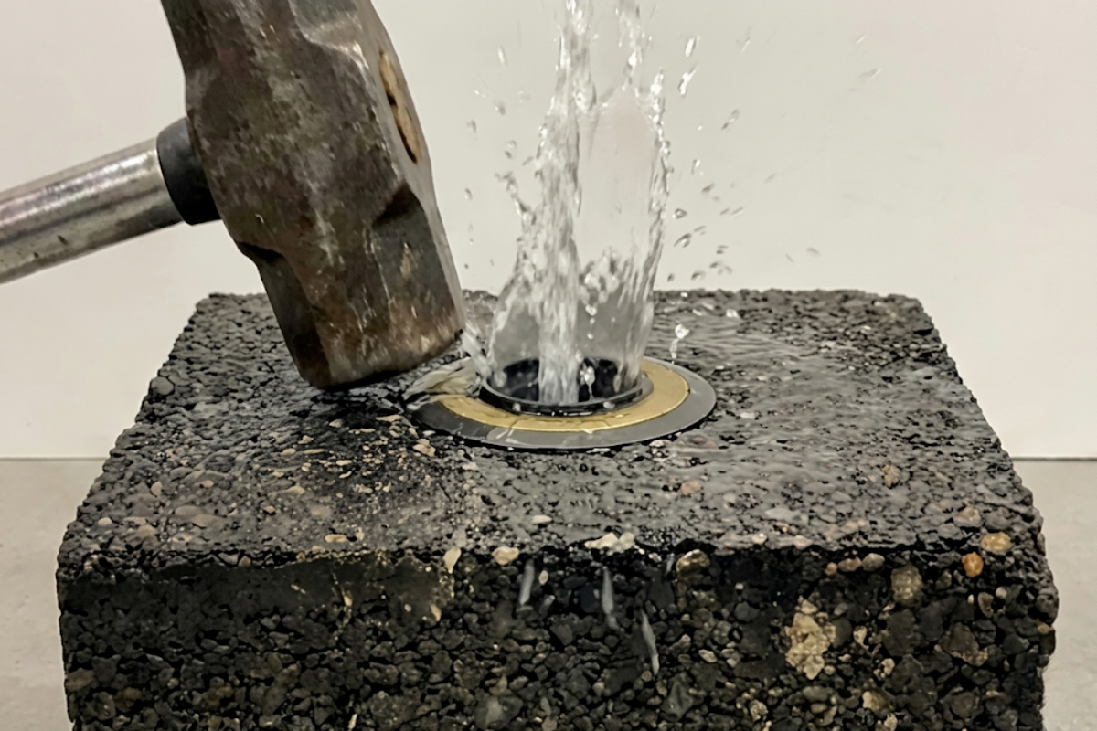
Surface Ejection (Load -Induced Displacement Test)
Immediate vertical ejection of trapped water. The device successful converts downward compressive mechanical load into a defined, upward vertical flow path.
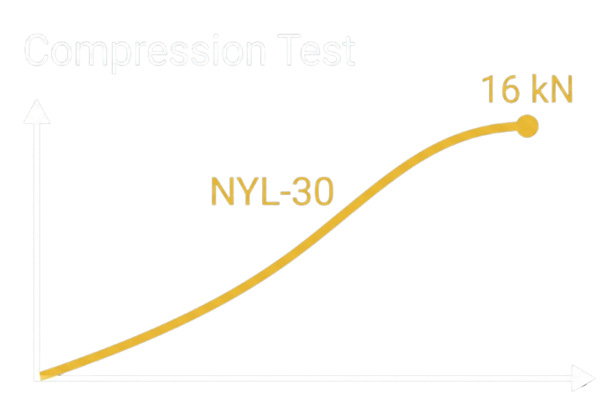
NYL-30 variant demonstrates superior load-bearing performance, achieving a peak load capacity of ~15–16 kN.
Maintains structural integrity longest, providing high strength and stiffness.
When saturated and frozen, expanding water is forced upward through the device and discharged safely onto the asphalt surface.
Result: Zero explosive cracking or lateral displacement within the asphalt body.